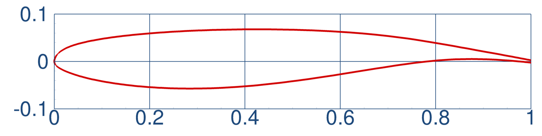
Verification 1: ONERA OAT15A Airfoil (Required)
| Working Group | Test Case |
|---|---|
| Sources of Scatter | 1a & 1c |
| Wind Tunnel Environment | 1a |
| Static Deformation (AePW) | 1a |
| Buffet (AePW) | 1a & 1b |
Objectives and Description
- Validation of steady CFD analysis grid convergence study and polar
- Users are encouraged to employ best practices
- Steady CFD (e.g., RANS)
- Multiple turbulence models can be submitted
- Grids
- Six-member grid family; four are required, six are desirable
- Use periodic boundary conditions for sidewall boundary conditions
- Encourage use of committee-supplied grids
- User-generated grids are acceptable (see guidelines)
- Flow Conditions
- Mach=0.73, Rec=3x10⁶, TStatic=271.K (487.8 R)
Test Cases
V1a: Grid Convergence and Polar
- Settings:
- Flow Conditions: α = [1.36°, 1.50°, 2.50°, 3.00°, 3.10°]
- Grid Levels: [1,2,3,4,5,6]
V1b: Extended Polar (Unsteady) [Buffet WG Test Case 1b]
- Settings:
- Unsteady analysis
- Flow Conditions: α = [3.25°, 3.40°, 3.50°, 3.60°, 3.90°]
- Grid Levels: [1,2,3,4,5,6]
V1c: Scatter Reduction Reprise [Scatter WG Test Case 1c]
- Additional Instructions for the Source of Scatter Working Group:
- Use updated grid families with common farfield (1000 chords away)
- French Vanilla SA-(neg) (All-terms)
- Sutherland's Law
- Adiabatic Wall (not isothermal)
- Converge residuals to machine precision (~1e-10)
- Additional Flow Conditions for the Source of Scatter Working Group:
- γ = 1.4, Pr = 0.72, PrT = 0.9
- farfield Χ = ν/ν~ = 3
Objectives and Description
- Validation of steady CFD analysis grid convergence study and polar
- Users are encouraged to employ best practices
- Steady CFD (e.g., RANS)
- Multiple turbulence models can be submitted
- Grids
- Six-member grid family; four are required, six are desirable
- Use periodic boundary conditions for sidewall boundary conditions
- Encourage use of committee-supplied grids
- User-generated grids are acceptable (see guidelines)
- Flow Conditions
- Mach=0.73, Rec=3x10⁶, TStatic=271.K (487.8 R)
- Six-member grid family; four are required, six are desirable
- Use periodic boundary conditions for sidewall boundary conditions
- Encourage use of committee-supplied grids
- User-generated grids are acceptable (see guidelines)
- Mach=0.73, Rec=3x10⁶, TStatic=271.K (487.8 R)
Test Cases
V1a: Grid Convergence and Polar
- Settings:
- Flow Conditions: α = [1.36°, 1.50°, 2.50°, 3.00°, 3.10°]
- Grid Levels: [1,2,3,4,5,6]
V1b: Extended Polar (Unsteady) [Buffet WG Test Case 1b]
- Settings:
- Unsteady analysis
- Flow Conditions: α = [3.25°, 3.40°, 3.50°, 3.60°, 3.90°]
- Grid Levels: [1,2,3,4,5,6]
V1c: Scatter Reduction Reprise [Scatter WG Test Case 1c]
- Additional Instructions for the Source of Scatter Working Group:
- Use updated grid families with common farfield (1000 chords away)
- French Vanilla SA-(neg) (All-terms)
- Sutherland's Law
- Adiabatic Wall (not isothermal)
- Converge residuals to machine precision (~1e-10)
- Additional Flow Conditions for the Source of Scatter Working Group:
- γ = 1.4, Pr = 0.72, PrT = 0.9
- farfield Χ = ν/ν~ = 3
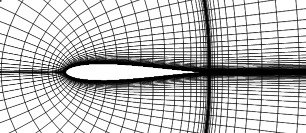
Verification 2: Joukowski Airfoil
| Working Group | Test Case |
|---|---|
| Sources of Scatter | 1b |
Objectives and Description
- Validation of steady CFD analysis grid convergence study
- Build on work of the High-Fidelity CFD Verification Workshop RANS WG
- Settings
- Steady CFD (e.g., RANS)
- French Vanilla SA-(neg) (All-terms)
- Converge residuals to machine precision (~1e-10)
- Adiabatic Wall (not isothermal)
- Sutherland's Law
- Grids
- Use python script to generate grid family (recommend Classic family)
- Six-member grid family; four are required, six are desirable
- Use periodic boundary conditions for sidewall boundary conditions
- Encourage use of committee-supplied grids
- User-generated grids are acceptable (see guidelines)
- Grids
- Six-member grid family; four are required, six are desirable
- Use periodic boundary conditions for sidewall boundary conditions
- Encourage use of committee-supplied grids
- User-generated grids are acceptable (see guidelines)
Test Cases
V2: Grid Convergence Study [Scatter WG Test Case 1b]
- Settings:
- Flow Conditions:
- Mach=0.15, Rec=6x10⁶, TStatic=520.0 R
- γ = 1.4, Pr = 0.72, PrT = 0.9
- farfield Χ = ν/ν~ = 3
- α = 0.0°
- Grid Levels: [1,2,3,4,5,6]
Objectives and Description
- Validation of steady CFD analysis grid convergence study
- Build on work of the High-Fidelity CFD Verification Workshop RANS WG
- Settings
- Steady CFD (e.g., RANS)
- French Vanilla SA-(neg) (All-terms)
- Converge residuals to machine precision (~1e-10)
- Adiabatic Wall (not isothermal)
- Sutherland's Law
- Grids
- Use python script to generate grid family (recommend Classic family)
- Six-member grid family; four are required, six are desirable
- Use periodic boundary conditions for sidewall boundary conditions
- Encourage use of committee-supplied grids
- User-generated grids are acceptable (see guidelines)
- Grids
- Six-member grid family; four are required, six are desirable
- Use periodic boundary conditions for sidewall boundary conditions
- Encourage use of committee-supplied grids
- User-generated grids are acceptable (see guidelines)
Test Cases
V2: Grid Convergence Study [Scatter WG Test Case 1b]
- Settings:
- Flow Conditions:
- Mach=0.15, Rec=6x10⁶, TStatic=520.0 R
- γ = 1.4, Pr = 0.72, PrT = 0.9
- farfield Χ = ν/ν~ = 3
- α = 0.0°
- Grid Levels: [1,2,3,4,5,6]
V2: Grid Convergence Study [Scatter WG Test Case 1b]
- Settings:
- Flow Conditions:
- Mach=0.15, Rec=6x10⁶, TStatic=520.0 R
- γ = 1.4, Pr = 0.72, PrT = 0.9
- farfield Χ = ν/ν~ = 3
- α = 0.0°
- Grid Levels: [1,2,3,4,5,6]
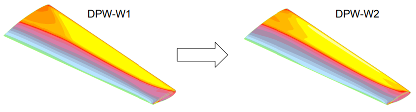
Verification 3: DPW-III Wing Increment: W1/W2
| Working Group | Test Case |
|---|---|
| Sources of Scatter | 1d & 1e |
Objectives and Description
- Validation of steady CFD analysis grid convergence study
- Repeat of DPW III W1 & W2 (20 years later)
- Users are encouraged to employ best practices
- Settings:
- Grids:
- Reference Parameters:
Test Cases
V3a: Grid Convergence [Sources of Scatter WG Test Case: 1d]
- Flow Conditions:
- Mach=0.76, Rec=5x10⁶, TStatic=580.0 R (322.22 K)
- γ = 1.4, Pr = 0.72, PrT = 0.9
- farfield Χ = ν/ν~ = 3
- α = 0.5°
- Grid Levels: [1,2,3,4,5,6]
V3b: Polar: [Sources of Scatter WG Test Case: 1e]
- Flow Conditions:
- Mach=0.76, Rec=5x10⁶, TStatic=580.0 R (322.22 K)
- γ = 1.4, Pr = 0.72, PrT = 0.9
- farfield Χ = ν/ν~ = 3
- α = [-1.0°, 0.0°, 0.5°, 1.0°, 1.5°, 2.0°, 2.5°, 3.0°]
- Grid Level: 3 or 4
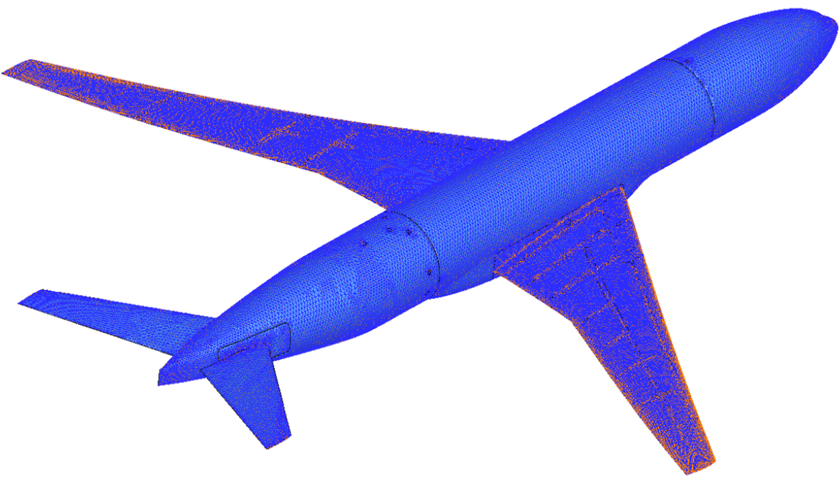
Verification 4: CRM FEM Validation
| Working Group | Test Case |
|---|---|
| Static Deformation (AePW) | 1b |
Objectives and Description
- Validation of provided NASA CRM Finite Element Model
Test Cases
V4: CRM FEM Validation [Static Deformation WG Test Case 1b]
- Settings:
Objectives and Description
- Validation of provided NASA CRM Finite Element Model
Test Cases
V4: CRM FEM Validation [Static Deformation WG Test Case 1b]
- Settings:
V4: CRM FEM Validation [Static Deformation WG Test Case 1b]
- Settings: